Friday, January 16, 2009

API 312 Project.

A while ago I bought 4 API 312 PCB kits from a guy on Craigslist, Chris, who had bought them from 3nity at Prodigy Pro. At that point I had done little in the way of electronics research or any real diy projects. A complete NOOB! I needed more mic pre's and I didn't have the money for quality brand name stuff so I set off to buy some project kits of reputably great sounding, fairly easy to build pre's. I kind of jumped in with 4 because I could take advantage of the a 1U case and a single power supply.

So I had the pcb kits (which were very simple to assemble) together in a few hours the day after I bought them. Ok, admittedly I asked Chris a pile of really stupid questions while assembling everything. After a a short time he just kind of stopped replying. Completely understood, heh heh, sorry for hassling you Chris.


That was at the beginning of November. It's now mid January and I'm finally pulling together the last pieces. Since then I've learned a lot about electronics and have answered a lot of the dumb questions on my own. Understanding how to properly power multiple loads with one power supply was a stepping stone. Understanding what makes a preamp sound different from another preamp was another.

Transformers and Op Amps

Instead of trying to accurately reproduce the original API 312 with the exact same transformers and 2520 opamps, I decided to follow 3nity's suggested use of Cinemag input and output transformers (same used in the A-Designs Pacifica which is a giant plus in my books). And after researching which opamp I decided on the John Hardy 990c. There are lots of opamp manufacturers out there that make a 990 DOA based on the original Jensen design that fits in the API 2520 footprint. It was down to the JLM and the Hardy. I ended up choosing (from what I read about them) the cleaner of the two. (There is a great list of 2520 compatible OpAmps at the Eisen Audio site http://www.eisenaudio.com/diy500/tables/opamps/). The Cinemag transformers and Hardy Opamps are in the mail right now. I should receive them any day now.

Voltage and Current Draw

In the mean time I did a bunch of reading on powering the preamps. Besides the +48 dc phantom supply, the opamp is what requires power on the preamp board. Therefore, the opamp defines the voltage required and the minimum current draw. The API 2520 and and all API VPR 500 series stuff requires +/-16 V. To some this is the downside of the 500 series because lower powered pre's supposedly have less headroom.

The Hardy 990c can operate from +/-15 Volts to +/- 24 Volts. I reckon I can test different voltages to see how true this theory of lower volts = lower headroom, but likely I will get it working somewhere in the neighborhood of +/-18 Volts and leave it there.

As John Hardy kindly informed me, the supply current draw of the 990c is 25mA unloaded, therefore the power supply needs to deliver +/-18Volts at 100mA. I was stuck on this question for a while.

The Power Supply

So the voltage and current draw questions had been solved, but what about the mains transformer? How does it play into the mix. I guess it was kind of working backwards because I had sorted out why I need a rectifier, regulator, etc. but the step down voltage from 110 to ? was the question. Actually, that's a lie, I still don't really understand +/- dc voltage. That's baffling.

With important questions left to be answered (questions that might jeopardize my safety when I power up... at least I know what not to do with electronics) I decided to buy a PSU kit from Five Fish Audio. Recommended by 3nity, it is an 18 - 24 volt regulated power supply with a step down transformer. It even has 4 separate outputs for 4 preamps. Pretty simple-stupid really.... awesome! Just right for a noob tech like me.

The package from Five Fish arrived yesterday so I quit talking to my girlfriend for the evening and got to work. Here's how it went...


The kit laid out. Construction begins...


Dammit! What?


Ok, finished. I was going to test the PSU but decided to wait 'cause it was getting late.

Laid it all out in case with incomplete 312 boards instead.
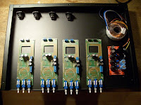

And... couldn't help myself, I had to start drilling the blank front panel.


2:30am, that's it for now.

Thursday, January 15, 2009

Jim Eno

I am a fan of Jim Eno. There, I said it. Drummer of Spoon, recording engineer and probably a really nice guy. His recordings are amazing and his dream studio is focking beautiful.

http://www.public-hifi.com/
www.myspace.com/publichifi

Youscope!

Youscope (oscilloscope demo)


More Videos & Games at Watch2Video

This is so damn cool.

http://watch2video.com/v/s1eNjUgaB-g/youscope-oscilloscope-demo.html

A .wav file that sounds like garbage, but when you apply the sound to the x/y of an oscilloscope it displays images. Almost like a... TV.

Rad.


DIY Oscilloscope

Added to this project you could make your own oscilloscope from a TV
http://koti.welho.com/aahone22/tvscope.html
or
http://www.hacknmod.com/hack/how-to-build-your-own-oscilloscope/

I tried to make one out of an old black and white tv. It seemed to work for a split second and then just died. Maybe there was a short or the tv was broken on the inside. Dunno, but I didn't attempt digging around near that massive capacitor to try to fix it. I'm sure I have some photos of my fail of an oscilloscope.

Wednesday, January 14, 2009

Shitsnap! My mouser order arrived

I came home to a box full of component fun stuff to stuff into my hungry pcbs. Not a complete box unfortunately but some necessary junk. I'm an idiot and was a bit too generous with the voltage ratings when I ordered the caps. I ended up getting caps that were waaaay to big for the board I'm putting them on. Shit!


The semi complete Maestro Brassmaster Fuzz. Still waiting on parts. So I got the little transformer which is marked to indicate it is directional, but there is no documentation of this on the GGG build instructions. Not sure if I should chance soldering it in place without confirmation.


Here is the semi-complete Maestro Ring Modulator with some empty holes to fill. I got the 14 pin IC (I think it's a multiplier chip) from http://www.arcadechips.com/ apparently it's really difficult to find. It didn't take Google very long to find one for sale online.

The only thing that I was able to use from the bunk Mouser order was the IC 741 opamp (black square closest to the bottom right of the pic)


Shin Ei Companion Fuzz: The Japanese Teeth


My second project, a diy fuzz pedal kit that I bought from General Guitar Gadgets. First I have to say that that site is a great resource, tons of diy kits and pcb boards to order and an active community to support the builds.

Ok. The Shin Ei Companion Fuzz build. I chose this to build for my friend Trevor's birthday present because he didn't have a down right dirty fuzz box and he likes Colin Greenwood/Kevin Sheilds.

I chose to opt out of getting the pre drilled aluminum enclosure that is available with all of the complete pedal kits at GGG. Why? Because I thought they looked a little thin and cheap and I thought that I could get a better box from my local electronics shop and drill it myself for cheaper than they were offering. Turns out it would have been cheaper and quality probably just as good if I bought the complete kit with enclosure from the site. Oh well, lesson learned.

I wish I had picture or video of me drilling the holes for the components. Once the drill gets far enough to get stuck, the box just flails and spins around everywhere. Ha! Trouble

The instructions were very comprehensive. The kit was complete. Got it done in about two hours. I will have to put up some mp3 samples, it sounds disgusting!


19 Channel Snake Mod: First Big Soldering Project


My first big soldering project started with a 100ft 16/4 Whirlwind snake that I bought from eBay. It was ragged, had channels that didn't work and it was too long for what I needed it for. What I decided to do was cut it into 3 pieces:

  • xlr box to trs fan
  • trs fan to xlr fan
  • xlr fan to xlr/trs fan

The purpose, to split the snake by a patchbay so I can hot patch (yes with the +48 off) to audition different mic pre's on different mics.

I found out quickly that this project needed a whole lot more time to complete than I set out with (I started on a Tuesday and I had to pack up and leave for a session on Friday. I work 9-5 so I stayed up til 3 every night soldering). 95 jacks doesn't seem like a lot, but it amounted to 285 solder points, quite a lot for a novice. Needless to say, I got good fast.

List of DIY Projects

Here is the run down of what I've been working on. Pictures and details to follow...

  1. Snake (Complete)
  2. Shin Ei Companion Fuzz (Complete)
  3. Maestro Brass Master Fuzz (Waiting on parts)
  4. Maestro Ring Modulator (Waiting on parts)
  5. API 312 4 Channel Mic Pre (Waiting on parts)
  6. Neve 33609 Stereo Compressor

My DIY Obsession

I am unable to conquer my diy electronics obsession! Studio tools have made me broke many times over, spontaneous craigslist and ebay buys are or were frequent. My resolution, turn to diy audio electronics. Cheaper, slower, learn more. Uhhh, well, unfortunately diy has just as tight a hold on my finances as buying name brand stuff. Most recently I ordered a Neve 33609 build from a guy on the prodigy-pro forum Yikes! after the conversion it ended up being $450 Canadian for the PCB set and very handsome silk screened case. Definitely not complaining, it just took me by surprise how quickly €200 ramped up to the Canadian equivalent.

Hello

So my audio obsession has now manifested itself as a blog. Woot! I have been pretty consumed with audio in one form or other for most of my life. Early instruments, hours/days/years of self taught theory, bands and more bands, studio and most recently diy audio electronics. The latter (and the helpful community around it) being the inspiration for this blog.